
Ever wonder why the meter still shows incorrect power readings even after double-checking your current transformers and potential transformers connection to your multi-function power meters? Here are a few steps to follow to verify your CTs and PTs connections and get the proper meter readings.
A good place to start: It's always helpful to estimate the system wattage before troubleshooting. If the PT and CT ratios are correctly entered, look at the line to line voltage (VLL) and multiply it by the line current (I). Then multiply that number by the square root of three and then again by the assumed power factor. This number is helpful when determining the correct watt reading. If the reading is off by more than 33% of your estimate, check the phasing and polarities (see "Here's a trick").
-
- Verify the required connections - is this 3P3W or 3P4W? Check your multi-function power meter datasheet for proper connections. If this is a 3P3W, you will need two current transformers (2 element) or three current transformers ( 2 ½ element) and two potential transformers with two bushings. The two potential transformers connect in an open delta configuration. If the connection is a 3P4W, you will need three current transformers (3-element) and three potential transformers with a single bushing, and the potential transformers connect in wye-wye ground connections.
-
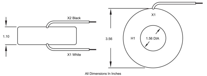
- Double-check the current transformer connections and verify the polarities are not reversed. The H1 primary side of the current transformer faces the source (or the line), and the X1 is the positive (the X2 is common).

- Double-check the current transformer connections and verify the polarities are not reversed. The H1 primary side of the current transformer faces the source (or the line), and the X1 is the positive (the X2 is common).
-
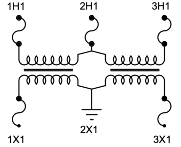
- Verify the primary and secondary connections are correct and the polarities are not reversed for the potential transformers. The high side (H) connects to the primary voltages, and the low side (X) connects to the secondary voltages. An example of the 3-phase open delta connection is the connection diagram of the 2VT460 PT below.

- Verify the primary and secondary connections are correct and the polarities are not reversed for the potential transformers. The high side (H) connects to the primary voltages, and the low side (X) connects to the secondary voltages. An example of the 3-phase open delta connection is the connection diagram of the 2VT460 PT below.
-
- Make sure the current and potential transformer phases are connected to the corresponding labeled connection points on the power meter. For example, the current transformer on phase A connects to the terminal of phase A of the meter. And, the 1H1 of the potential transformer is connected to the phase A terminal on the meter. The same applies to the remaining phase B and phase C.
-
- Check the power meter CT and PT ratio configuration making sure they match what you are using. If you are in a rush and have the current transformers but not the matching potential transformers (example: you need 480:120v, but you have 600:120v PTs), you can still use the 600:120v potential transformers and, as long as you enter the correct potential transformer ratio of 600:120v in the configuration of the meter, you will still get accurate voltage and power readings. (Note: check with your utility if this set-up is acceptable for revenue grade metering).
Here's a trick if your watt reading seems low: Short circuit all the CT secondaries. View the watt reading, it should be very close to zero. Once verified, remove one the CT shorts. Did the watt reading increase (positive reading)? If not, the CT secondary wires need to be rolled (reversed). If the reading did increase, go ahead and remove the second CT short, did the watt reading increase? If so, proceed to the next CT short. Once the watt reading increases each time, the CT polarity is correct (refer to item #4).

Current Transformers
Browse our complete inventory of 1-5 A and 0.333-1 V current transformers and find the right CT for your application.

Potential Transformers
FLEX-CORE® maintains a large in-stock inventory of Potential Transformers including Low Voltage and Medium Voltage Potential Transformers for most common applications.